
What Is a GREE H5 Error Code? IPM Protection, Causes, and How to Diagnose It
| A GREE H5 error code indicates IPM (Intelligent Power Module) protection: the system has detected either an IPM synchronization issue or an overcurrent condition. Before replacing the board or compressor, check the basics first: indoor and outdoor airflow, refrigerant charge and pressure (using a PT chart), and tight wiring. The GREE Service Tools can speed diagnosis. Always identify the root cause before replacing the compressor or the new compressor will fail too. |
Download the Complete E5 Troubleshooting Guide
Get the full step-by-step E5 error code troubleshooting guide in PDF format for easy reference in the field:
Download E5 Troubleshooting Guide (PDF)What Does the GREE H5 Error Code Mean?
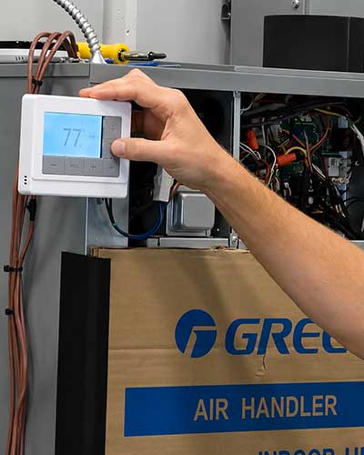
A GREE H5 error code is displayed on the indoor unit and indicates IPM (Intelligent Power Module) protection. The system has detected either an IPM synchronization issue or an overcurrent condition: if the IPM does not provide adequate power to the Drive Chip, the system shuts down to protect itself. See the GREE Troubleshoot Error Codes hub for the full library of GREE diagnostic codes.
How GREE Mini-Splits Convert Power to the Compressor
Power conversion in a GREE mini-split flows from the incoming 230 volts AC, through the bridge rectifier, into the Power Factor Correction (PFC) module, and then through the Intelligent Power Module (IPM) which converts the voltage and powers the compressor. The PFC module sends electrical pulses to the compressor and receives DC voltage typically in the range of 290 to 340 volts DC. That DC voltage is split into three separate pulses, one per compressor phase.
How the System Detects an H5 Condition
The outdoor main control board monitors three indicators on the PFC module: output voltage, output current, and PFC module temperature. If the PFC output current is too high, the system displays the fault as an H5 over-current error. A failure in any of those monitored indicators tells the system the PFC module is faulty and needs to be replaced.
What Causes a GREE H5 Error Code?
The H5 error has multiple possible causes that range from installation and refrigerant issues to drive board electrical faults to a failed compressor. Work the basics first. Most H5 calls do not require a board or compressor replacement once airflow, refrigerant charge, and wiring are verified.
Potential H5 Root Causes
- Compressor wiring loss of phase or phase reversal.
- Current to the compressor is too high (overcurrent).
- The drive board IPM module 15-volt power supply is below 13.5 volts.
- The drive board six-line pulse width modulation (PWM) signal and its corresponding element are faulty.
- The drive board compressor current sampling element, or the Drive Chip current sampling AD terminal, is faulty.
- The compressor itself is bad (open winding, shorted to ground, or seized).
- Non-condensibles in the refrigerant system: standing pressure does not match outdoor temperature on the PT chart.
- System overcharge or undercharge of refrigerant.
- Restriction or kinked refrigerant line.
- Inadequate airflow at indoor or outdoor coil.
- Crossed piping between zones (multi-zone systems).
- Faulty thermistors: See the GREE thermistor ohm chart here.
- Heat-sink paste / screws on the main board are not properly seated, so heat does not transfer to the heat sink (commonly causes a newly-replaced board to fail).
How Do I Troubleshoot a GREE H5 Error Code Step by Step?
Start with airflow and installation, then refrigerant pressures, then wiring, then compressor windings, then the drive section of the board. The same order matters whether the unit has just been installed or has been running for years.
Step 1: Verify Airflow and Installation
- Confirm indoor filters, coils, and blower wheels are clean.
- Confirm the outdoor coil is clear of debris with proper clearance around the unit.
- Verify all service valves are open and the system has been properly evacuated.
Step 2: Check Refrigerant Pressure Against the PT Chart
Check standing pressure against outdoor temperature using the PT (pressure-temperature) chart for the system's refrigerant. If the pressures do not match what the chart predicts for the ambient, the system may have non-condensibles, which can directly cause an H5 error. Recover, evacuate, and recharge if non-condensibles are confirmed.
Step 3: Inspect Wiring and the Main Board
Inspect the wiring against the unit's diagram and check the main board for visible damage. All screws on the board must be installed and tightened so heat transfers correctly through the thermal paste to the heat sink. Missing this step is a common reason a newly-replaced board fails on the first run.
Step 4: Test the Compressor Windings
Power off the system and unplug the leads at the compressor. Set the meter to ohms and test the windings phase-to-phase between U-V, U-W, and V-W. Readings should be roughly equal across the three pairs, typically in the 0.3 to 2 ohm range on FLEXX R32 compressors, and 3 to 4 ohms on other R32 mini-split compressors. If you're uncertain which range applies to the model in front of you, call GREE technical service at 888-850-7928 before condemning the compressor.
Then test each winding to ground. Resistance to ground should be infinite (open line). A measurable ohms reading to ground indicates the compressor is grounded. A mega-ohm reading to ground does NOT indicate a grounded compressor.
Step 5: Restart and Check Compressor Amperage
Restore power and restart the system. If the compressor does not start, check amperage on all three legs. If amperage is present on each leg but the compressor will not start, the compressor is likely seized. If there is no amperage on one or more legs, the main board has failed. Timing matters when reading amps: the system runs the condenser fan for about 30 seconds before trying to start the compressor, and the start attempt only lasts a few seconds before the unit drops out. You are only looking for some kind of amp draw on that leg, which can be anywhere from roughly 0.3 or higher. After the unit drops out, wait for the condenser fan to cycle back on before testing the next wire, and repeat for each leg.
Step 6: If the Compressor Runs but Still Trips H5
If the compressor runs but the system trips H5 once it ramps up, the cause is most likely one of: system overcharge, refrigerant restriction, a kinked refrigerant line, inadequate airflow, crossed piping (on multi-zone systems), or a faulty thermistor. Verify each of these before assuming a drive-section electrical fault.
How Do I Test the Drive Section of the Board for an H5 Fault?
Drive-section testing on the main board has four parts: a K-ohms resistance test between the P (positive) and N (negative) bus terminals and each compressor phase, a diode test on the same points, a powered DC voltage test between P and N, and a powered AC voltage test between L (live) and N (neutral). All four tests together confirm the bridge rectifier, PFC module, and IPM are good.
K-Ohms Resistance Test Steps (Power Off)
- Power off the system.
- Set the meter to K-ohms.
- Measure resistance between P and U, P and V, P and W, N and U, N and V, and N and W.
- All six readings should be above 10 K-ohms with no large differences between them.
Diode Test Steps (Power Off)
- Power off the system.
- Set the meter to diode test mode.
- Place black lead on P, red lead on each of U, V, and W in turn.
- Place red lead on N, black lead on each of U, V, and W in turn.
- All six readings should be between 0.3 volts and 0.7 volts.
Powered DC Voltage Test Steps (P to N)
- Restore power.
- Set the meter to DC volts.
- Test the discharge points P (positive) and N (negative) on the board.
- Voltage should be between 290 and 340 volts DC.
Powered AC Voltage Test Steps (Power Supply L to N)
- Set the meter to AC volts.
- Test the L (live) and N (neutral) terminals of the power supply on the PCB.
- Voltage should be between 187 and 253 volts AC for a 230 V unit, or between 103 and 126 volts AC for a 115 V unit.
- In the U.S., L1 = 115 V and N = L2 (the other side of 230 V). Outside the U.S., 230 V is sent straight to L1.
- Use the board diagrams in the unit's service manual to locate the test points on the boards.
Performing all four checks confirms the bridge rectifier, power factor correction module, and intelligent power module are good. If any reading is out of range, that section of the board is the fault and the board needs to be replaced.
Quick Reference: Healthy H5 Test Values
| Test | Meter Setting | Test Points | Healthy Reading |
|---|---|---|---|
| Compressor windings (phase-to-phase) | Ohms | U-V, U-W, V-W | FLEXX R32: 0.3 to 2 ohms. Other R32 mini-split: 3 to 4 ohms. Equal or within .01 ohms from one to the other. |
| Compressor windings to ground | Ohms | U, V, W to ground | Infinite (open line) |
| Drive section resistance | K-ohms | P-U, P-V, P-W, N-U, N-V, N-W | Above 10 K-ohms, no large differences |
| Drive section diode | Diode | P-U, P-V, P-W, N-U, N-V, N-W | 0.3 V to 0.7 V at all six points |
| Bus DC voltage (powered) | DC volts | P (+) and N (-) on board | 290 to 340 V DC |
| Power supply AC (powered) | AC volts | L and N on PCB | 187 to 253 V AC (230 V) 103-126 AC (115 V) |
Why Should I Always Identify the Root Cause Before Replacing the Compressor?
When replacing a compressor on a system that threw H5, always identify the root cause: overcharge, undercharge, restriction, or airflow problem. Otherwise it is only a matter of time before the new compressor fails the same way. The compressor is rarely the actual root cause of an H5; it is most often the casualty of a refrigerant or airflow condition that is still present after the swap.
Frequently Asked Questions About the GREE H5 Error Code
What does H5 mean on a GREE mini-split?
H5 indicates IPM (Intelligent Power Module) protection. The system has detected either an IPM synchronization issue or an overcurrent condition and shuts down to protect itself. The error displays on the indoor unit. See the GREE Troubleshoot Error Codes hub for related codes.
What is the most common cause of a GREE H5 error?
Most H5 calls trace back to airflow, refrigerant charge, or refrigerant pressure issues, not a failed board or compressor. Always check indoor and outdoor airflow, service valves, and standing pressure against the PT chart before assuming an electrical fault.
What should the compressor windings read on a healthy GREE mini-split?
Phase-to-phase (U-V, U-W, V-W) should read approximately 0.3 to 2 ohms with equal or within .01 ohms across all three pairs on FLEXX R32 compressors. On other R32 mini-split compressors, the same phase-to-phase test should read approximately 3 to 4 ohms, equal or within .01 ohms across all three pairs. If you're uncertain which range applies to the model in front of you, call GREE technical service at 888-850-7928.
Does a mega-ohm reading to ground mean the compressor is grounded?
No. A mega-ohm reading to ground does not indicate a grounded compressor. Only a measurable ohms reading from the windings to ground confirms the compressor is grounded.
What DC voltage should the P and N bus terminals read on a healthy board?
290 to 340 volts DC, measured with the meter on DC volts between P (positive) and N (negative) with the system powered. A reading outside this range indicates the bridge rectifier or PFC section of the board is faulty.
What can cause a newly-replaced board to fail on a GREE mini-split?
Heat-sink paste and screw torque. All board screws must be installed and tightened so heat transfers through the thermal paste to the heat sink. Missing or loose screws prevent heat transfer and the new board can fail quickly.
Can refrigerant problems cause a GREE H5 error?
Yes. Non-condensibles in the system, an overcharge, an undercharge, a restriction, or a kinked refrigerant line can all trigger H5 once the compressor ramps up. Check standing pressure against the outdoor temperature using a PT chart before assuming a drive-section fault.
Should I replace the compressor when I get an H5 error?
Not until you identify the root cause. Most H5 errors are not actually caused by a failed compressor. Always identify whether the underlying problem is overcharge, undercharge, restriction, or airflow before swapping the compressor. Otherwise the new compressor will fail.
How does the system actually detect an H5 condition?
The outdoor main control board monitors three things on the Power Factor Correction (PFC) module: output voltage, output current, and module temperature. If the PFC output current is too high, the system reports H5 as an over-current error. A failure in any of the three monitored indicators tells the system the PFC module needs to be replaced.
For Additional Insights On the H5 Error Code:
Watch this detailed diagnostic walkthrough: